Steam Installation Tips
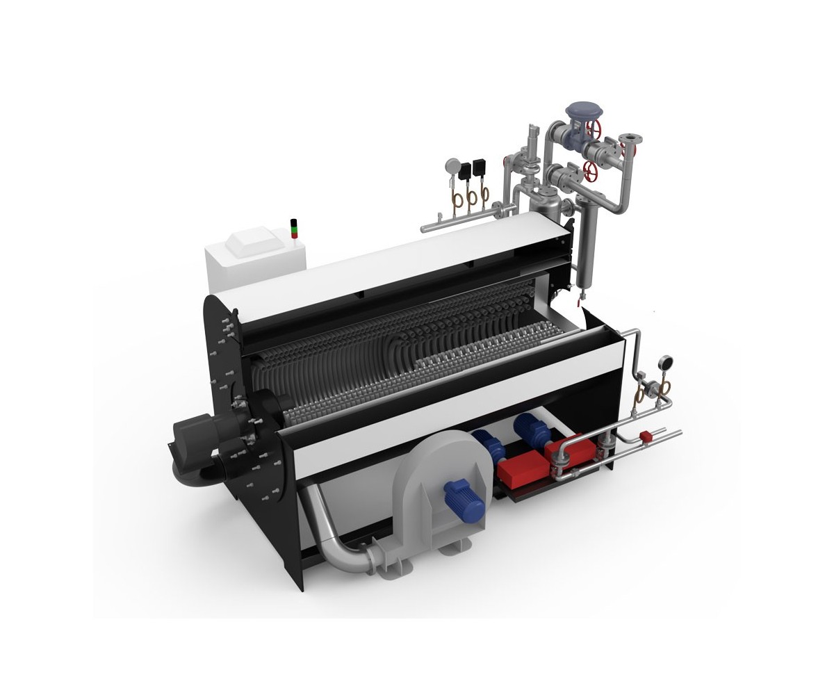
1. Separator
 The separator (water separator) , which is recommended to be used before the devices at the boiler outlet and main line inlets, holds the water particles that are dragged along with the steam. In this way, drier steam is provided to the system. By using the steam in a dry way, efficiency increases, product quality increases in processes where direct steam is sprayed, and the life of the fixtures in the installation is extended by preventing the corrosive and abrasive effect of water.
For a definitive solution to water entrainment problems in steam boilers, it is recommended to use separators at the boiler outlets.
2. Steam Collector
 The collector is the unit where steam is distributed. The steam trap to be used in collectors must discharge the condensate as soon as it is formed and must be resistant to severe conditions. The most suitable steam trap type for collectors is thermodynamic.
Collector diameter is determined by the formula Dcollector=√ ((DValve1)²+ (DValve2)²+ (DValve3)²+ (DValve4) ²).
Condensate discharge should be provided by making a condensate pocket in the collectors, where the condensate can be easily discharged, as shown in the figure.
In collectors, inputs should be on one side and outputs should be on the other side.
Condensate pockets should not be located below the inlets or outlets.
3. Main Steam Line – Condensate Pockets
 The ideal distance for condensate pockets in steam transport lines is 30 - 50 m. Condensate formed in the main line should be drained by making pockets at appropriate intervals. In addition, condensate that will accumulate in elbows during line rises should also be drained.
The condensate collection (pocket) diameter is the same as the nominal diameter up to DN100 mm pipe; for larger diameters, two diameters smaller are selected.
In steam transport lines, the most resistant steam trap to atmospheric conditions and water hammers is the thermodynamic type.
4. Air Problem and End of Line Air Thrower Application
Air vents should be used at the ends of the lines in the installation. This is necessary for the system to heat up quickly and for steam to reach the units more quickly. Otherwise, air trapped at the ends of the lines will make steam emission difficult.
5. Units Line Design
 Dry steam is needed for the best efficiency in steam installations. In steam distributions from the main steam line to the units, branches should always be made from the top. If made from the bottom, water will flow with the steam.
STEAM TRAPS
Steam traps are one of the most important fixtures of steam installations. Mistakes that can be made in steam trap selection and line design will cause the efficiency of the system to decrease and the fixtures to fail in a short time. In addition, steam leaks caused by steam traps bring a lot of financial burden to the businesses. Therefore, choosing the most suitable steam trap for the process is one of the biggest steps in energy saving. Accordingly, the line design should be made in a way that will not prevent the operation of the steam traps.
It is recommended to use a strainer before the steam traps and a check valve after them. It should not be forgotten that thanks to these fittings, the life of the steam traps will be extended and the system will work healthily.
An example of a trap connection diagram is shown below. In fact, the fixtures and order in which a trap should be installed are shown in the figure. It will be useful to design accordingly.
 1. Ball Valve 2. Strainer 3. Steam Trap 4. Check Valve 1. Ball Valve
The strainer here is used to hold the deposits formed by the condensation of steam in the condensate lines, while the check valve prevents the back pressure in the steam traps discharging in the same line and increases the discharge capacity. At the same time, it will prevent the backflow due to vacuum from damaging the steam traps.
We recommend that you pay attention to the diagram when installing your steam trap.
We can explain steam traps by reviewing their working principles as follows:
Thermostatic Steam Trap
 This type of steam trap is also known as encapsulated steam trap. Thermostatic steam traps can discharge condensate 10 to 30°C below the evaporation temperature. For example, since the evaporation temperature is 165°C in 6 bar processes, these steam traps discharge condensate below 135°C. Condensate above this temperature remains in the line and coils, forming a layer that prevents heating. The resistance of a 1 mm water film against heating is equal to the resistance of approximately 0.5 meters of copper. Therefore, especially in coil systems, water must be removed from the system as soon as it forms.
In addition, this water layer both prevents heat and causes water hammers, causing holes in connection fittings and even serpentines.
Inverted Bucket Steam Trap
This type of steam trap, although it discharges the condensate as soon as it is formed, is insufficient to discharge the air.  Since air is a much stronger insulator than water, air that cannot be discharged will delay heating considerably. The resistance of a 1 mm air film against heating is equal to the resistance of 13 meters of copper. In addition, since steam cannot enter the area where the air is located, the steam volume decreases. This also affects efficiency.
Float Steam Trap
 The float trap removes air from the system thanks to the air discharge element within it. With the help of the float, the condensate is removed from the process as soon as it is formed and the heating of the system is accelerated. The discharge temperature is at the steam temperature. Due to these features, the float trap is the most suitable type of steam trap in serpentine/plate heaters, air conditioning plants, dyeing machines and cylinder sanforizers.
Thermodynamic Steam Trap
Due to its robust structure, it is preferred in main steam lines, line ends and collectors. In addition, it has high thermal efficiency as it discharges the condensate as soon as it is formed. Due to these features, this type of steam trap should be used in line ends and collectors. Discharge will be provided  .
.

